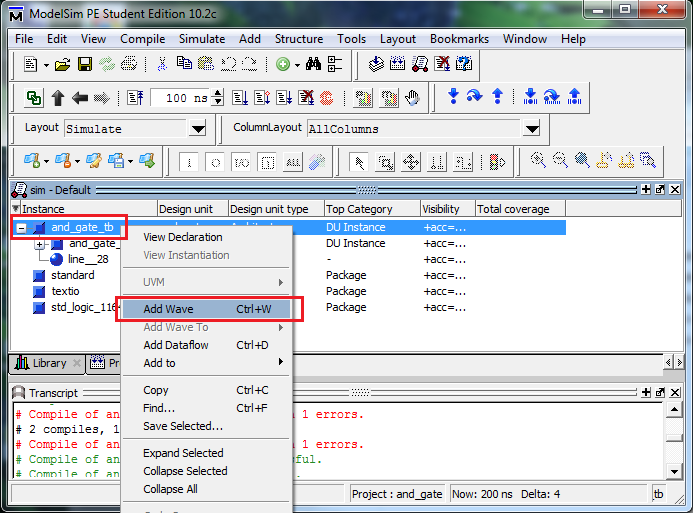
- #Generate a test bench with modelsim pe how to
- #Generate a test bench with modelsim pe software
- #Generate a test bench with modelsim pe code
#Generate a test bench with modelsim pe software
Second Example Delay Line Download it from HL and run on your own.ModelSim SE/PE Software Step 2: Create a New Library
#Generate a test bench with modelsim pe how to
How to use ModelSim? (cont’) Copy the relevant signals to the wave window Run simulation (Simulate->Run->Run) Work the right way… so u won’t loose grade: Ĭhange signal names to friendly ones (Display Names) Use “Dividers” between signals Mark time periods Zoom on the right signals Use Hexadecimal notations when necessary Save the wave format to use it later (“File->Save) (double-click on the configuration link of the complied test bench in “work” library)Īdd a new wave window (“View->New Window->Wave”) vhd files (“Compile->Compile All”) Load the “test bench” configuration file. vhd files Set compilation order (“Compile->Compile order”) Compile all the. Simulating Delays architecture rtl of and2 is begin c Add to Project”) Edit. sample_package.vhd library IEEE use IEEE.STD_LOGIC_1164.ALL PACKAGE sample_package is component nand2 port(a,b : in std_logic c : out std_logic) end component component not_gate port(a : in std_logic b : out std_logic) end component end sample_package In design files add : use WORK.
#Generate a test bench with modelsim pe code
Packages Saves time on component declaration, no need for code duplication. entity latch is port (s,r : in std_logic q,nq : out std_logic) end latch architecture dataflow of latch is begin q reset, clk => clk, d => d(i),q => q(i)) end generate end struct In other words we describe how signals flow through the circuit. VHD File Structure - Library Definition library ieee use ieee.std_logic_1164.all use IEEE.std_logic_unsigned.all - Entity Definition entity counter is port (clk : in std_logic q : buffer unsigned (7 downto 0)) end entity - Architecture Definition architecture rtl of counter is - Component and signal declaration Begin - Design Body process (clk) begin if (rising_edge(clk)) then q b, c=> nand_out) U2 : not_gate port map (a=> nand_out ,b=>c) end struct ĭata Flow Architecture Circuits are described by indicating how the inputs and outputs of built-in primitive components (ex.

VHDL Design Design must have a top level entity with : Īt least one input (test-bench is an exception) At least one output (test-bench is an exception) Optional Parameter (generic variable)Įach entity is located in separate file File is with.

Test Bench Generic Variables Generate Loops Packages and Simulating Delays Structural Dataflow Behavioral (Process, examples) Introduction to VHDL Very high speed integrated circuits Hardware Description Language Entities Architectures Tco1+TpdMin > Th2+tskew FF (Tco1,Tsu1,Th1) Logic Timing Tpd : Time from state change at input to state change at outputĭFF Timing Tco : Time from clock rise to output state change Tsu : Time that input must be stable before clock rise Th : Time that input must be stable after clock rise tsetupthold Clk DĬalculating Frequency Long Path Rule (Setup):ġ/FMax = Tco1+TpdMax+Tsu2+tskew Short Path Rule (Hold): Objectives Course Website, Software and Hardware Logic Timing Introduction to VHDL ModelSim Simulation First Assignment DefinitionsĪnnouncements Assignments Lectures Forums Anyone can ask Anyone can answer (if he knows the answer) Check Google before asking at forum.Īt the forums Monday 1600-1700 - Scheduling by email Email : Ĭourse Hardware Altera DE1 FPGA Board Cyclone II EP2C20F484C6 FPGA 50MHz,27MHz and 24MHz oscillators 4 pushbutton switches 10 toggle switches 10 red LEDS 8 Green LEDs


 0 kommentar(er)
